Parameter Panel
Click the locked model surface in the scene, or use the "Material Picker" tool (shortcut key: I) to sample the model surface, you can select the material, at this time, in the right panel, the corresponding inspector will appear.
The Material inspector contains the Basic tools, the Material Template drop-down menu, the Invisible in raytracing option, the mapping roll-out, and the UV roll-out.
Basic tools
There are three basic tool buttons:
Duplicate
Duplicate the currently selected material parameters, you can assign this same material to other surfaces.
Add to local
Add the currently selected material to your local library. You can find the saved materials in Assets>Local>Material drop down.
Reset
Restores the material parameters to their initial state (when the project file was just opened or when the material was assigned to the model surface).
Batch import PBR textures
Material Template
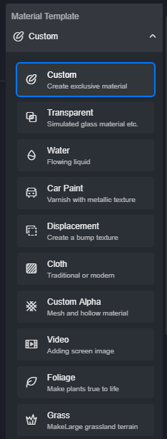
D5 Render currently has 10 material templates, click on the drop down menu to see the full list:
Invisible in raytracing
The "Invisible in raytracing" option controls whether or not the material participates in lighting (diffuse light, to be exact) calculations. When this option is checked, the material will be visible in camera and other material reflections, but will no longer cast shadows and bounce light.
If the material has "Emissive" turned on, the emissive light will disappear when "Invisible in raytracing" is checked. The Emissive effect is only visible in the camera and material reflections.
UV
This is the global UV control parameter, so it will be explained first. These parameters are involved in each mapping channel in the following section.
Stretch
stretch the texture map along the UV direction. The larger the value, the more the texture repeats per unit area, which appears to be the effect of "shrinking" the texture. The texture aspect ratio is locked by default, you can unlock it and stretch it separately in a certain direction.
Offset
offset the texture map along the UV axis.
Rotate
Rotate the texture on the plane, the value range is 0-360°.
Triplanar
When this option is turned on, for complex objects with chaotic UV coordinates, a continuous and uniform texture mapping is obtained.
Blend Amount
Let the texture seams created by Triplanar blend together.
Map
Base Color/Base Color Map
The Base Color parameter controls the color properties of the material itself.
When the material is metal (Metallic = 1), it is the reflection color of metal.
When the material is non-metal (Metallic = 0), it is the Diffuse Color of the non-metal.
The base color palette can only define a single color for the material, if you want more complex variations, you have to use a texture to control the color of the material, click on the "Base color texture" tab, then click on the texture slot to load the texture file:
If you are using PBR textures, maps with keywords such as "Color", "Base Color", "Albedo", "Diffuse", etc. in the filename are the base color of the material, usually linked to the "Base Color Map" slot.
In D5 Render, when there is a map in the "Base Color Map" slot, the color in the "Base Color" palette will blend with the map color, and the color blend mode is Multiply.
If you want to use the original color of the "base color map", make sure that the "base color" palette is pure white.
Click the "Detailed Parameters" button on the right side of "Base Color Map" to expand the base color map editing panel.
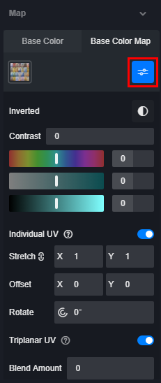
Basic color map detailed parameters
Inverted
Invert the color of the map. The hue will become a complementary color. Brightness will be reversed
Contrast
Increase or decrease the contrast of the image. Decreasing the contrast will make the image tend to be gray.
Hue
Pans the hue of the map on the hue ring, the control range is -180°~+180°, the adjustment range covers the whole hue ring.
Saturation
Adjust the saturation of the base color map. When the parameter is pulled to the lowest level, the map will become "black and white", and when the parameter is pulled to the highest level, the map will be very "vivid".
Brightness
Adjust the brightness of the base color mapping, pull the parameter to the lowest, the mapping will become black, pull the parameter to the highest, the mapping will become white.
Individual UV
When this option is turned down, this texture has a separate UV. You can stretch, offset, and rotate it individually, or you can use Triplanar mapping. This function is suitable for cases where you want to adjust a texture channel individually. For example, when you want to pan the base color map while keeping the normal bump unchanged.
Normal
Use normal mapping to make the material surface bumpy without additional modeling work. Normal maps usually look like this:
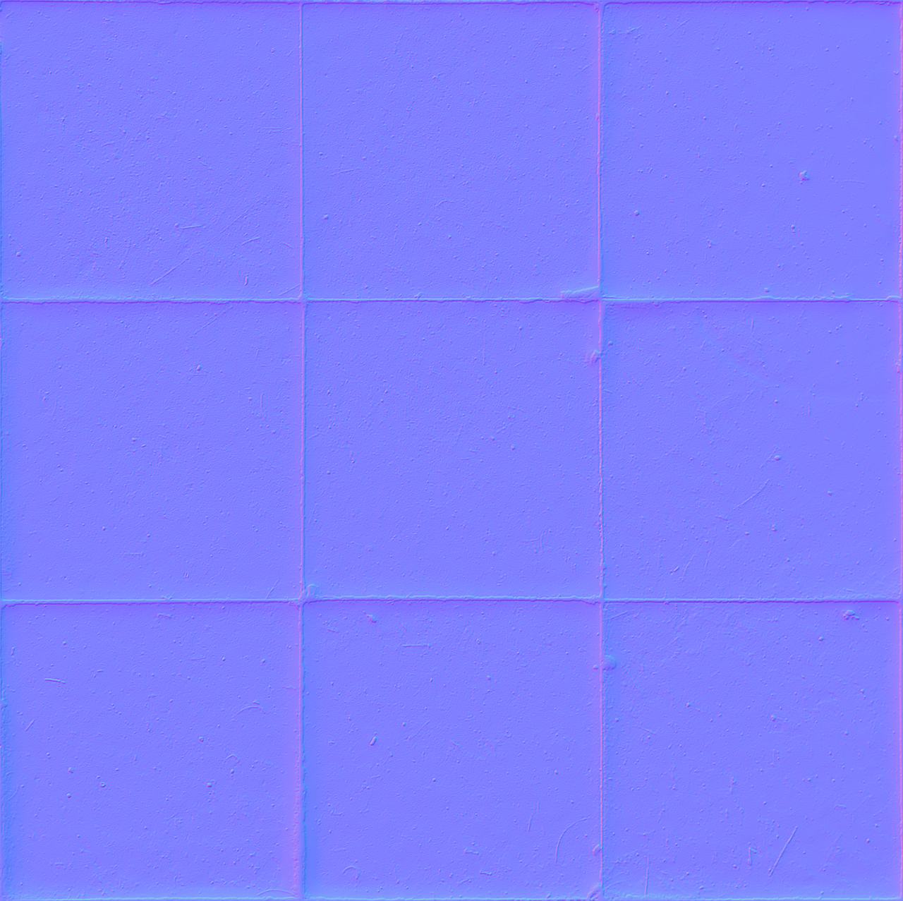
If you are using PBR textures, the "blue-purple" image with "Normal" in the file name is the normal map and should be linked to the "Normal" map slot.
Auto-Generated Normal map
In D5 Render, even if the user does not have a normal map, D5 automatically generates the normal information based on the base color map to make the material appear bumpy. As shown below, the normal slot is empty and D5 automatically generates the normal information based on the base color map, so you can adjust the strength of the bump effect through the controls. (For demonstration purposes, the base color mapping was temporarily adjusted to gray.)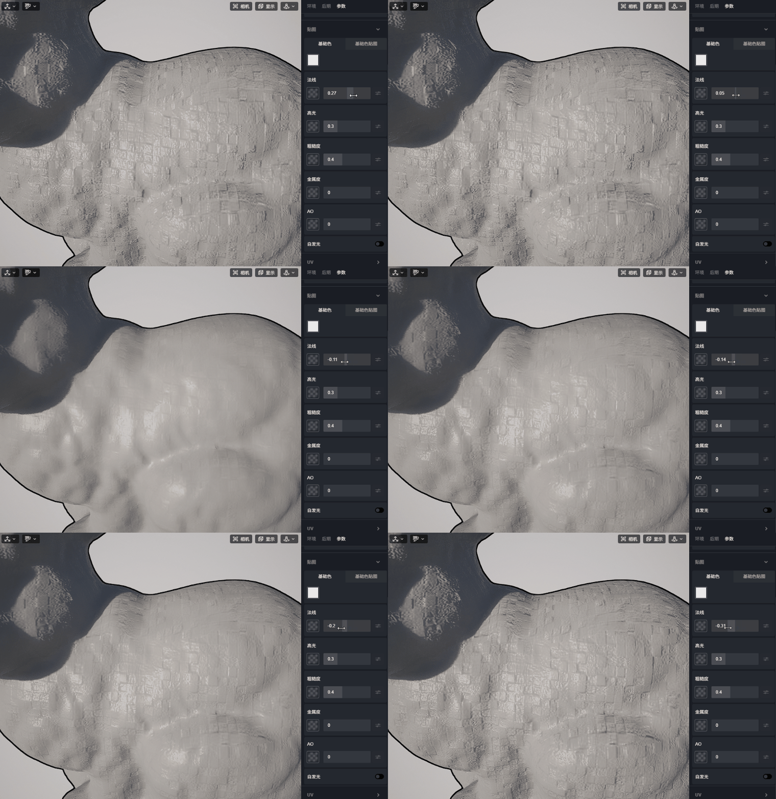
Normal Intensity
Adjust the normal intensity control to enhance or diminish the normal bump effect, or even pull left to enter a negative value to flip the bump effect.
Normal map detailed parameters
When there is a map in the Normal map slot, click the "Detailed parameters" button to expand the Normal map editing parameters panel.
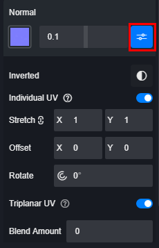
Inverted: flip the direction of the normal.
Individual UV: This parameter serves the same purpose as the base color map detailed parameter.
Triplanar UV: This parameter serves the same purpose as the detailed parameters of the base color map. Note that if the base color map has Individual UV and Triplanar UV turned on, the normal map also needs to have these turned on and the same parameters entered to match the base color map. Of course, if you want the normal mapping to be aligned with the base color mapping from the start, the correct workflow is: Do not turn on individual UV for each channel, use the Triplanar in the global UV control of the material.
Specular
This parameter controls the Reflectance of non-metal materials. It is a parameter designed to make it easier for artists to adjust the reflection of the material.
When Metallic=1, the Specular parameter has no effect on the material.
When Metallic=0, the Specular parameter affects the Reflectance of the material.
Due to the Fresnel Effect, when the light hits the surface of the material perpendicularly, the reflected light is the least. This is referred to as F0(Fresnel Reflectance at 0 Degrees). This means that when the camera or observer looks at the surface of the material perpendicularly, they will see the weakest reflectance.
When "Specular" =0, the material F0 is also 0%. The material has no specular reflection, only diffuse.
When "Specular" =1, the material F0 is also 8%. This is the highest reflectance of non-metal materials, usually gemstones, jade will reach this value.
Specular value 0-1 corresponds to F0 0%-8% linearly. For example, Specular=0.5 means that the F0 reflectance value is 4%.
Most of the non-metal material F0 between 2% to 5%, which translates into a Specular value of 0.25 to 0.625. In other words, when making non-metal materials, the minimum Specular should not be lower than 0.25. Water Specular parameter is 0.25, most of non-metal materials (glass, plastic, etc.) Specular value is about 0.5, gemstones, jade Specular parameter can be set to Specular=1.
Roughness
This parameter describes the microscopic roughness of the material surface, which macroscopically affects whether the reflection is blurred or not.
low roughness means that the surface is flat, the reflection effect of the material will be closer to a mirror. The overall material will have a clear reflection.
When the roughness increases, the material surface will become irregular, the reflected direction will vary randomly. The overall material will have a blurred reflection.
"Roughness" is the opposite of "glossiness". Theoretically, if you invert a "glossiness map", you will get a corresponding "roughness map".
Roughness map
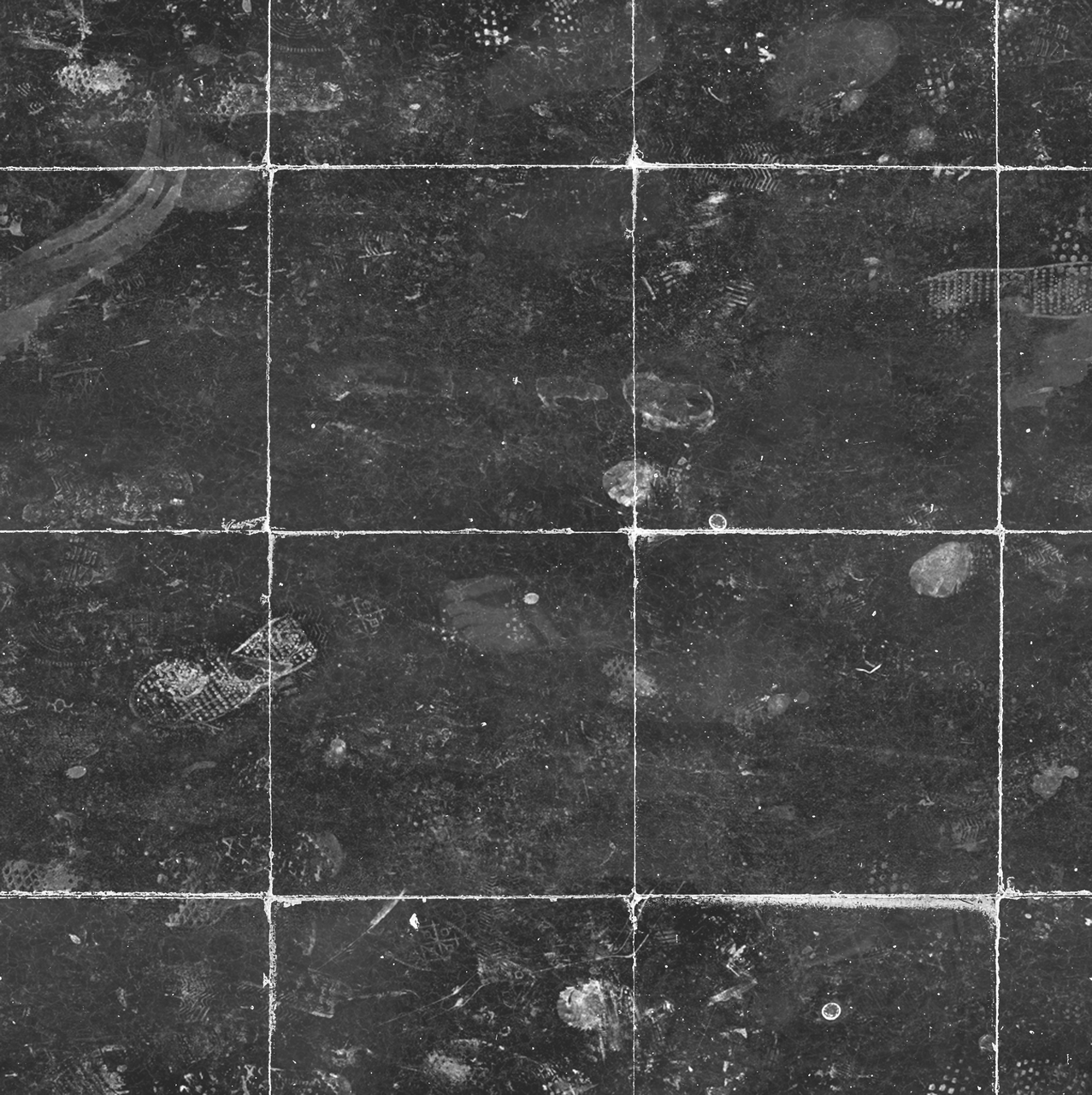
Many material surfaces are complex and we cannot define the entire surface with just a single roughness value. For example, a floor tile covered with dirt. The surface of the floor tile is smoother and has a lower roughness, while the roughness values of dust, dirt and brick joints will be higher.
Roughness map values range from 0 to 1, corresponding to a pixel change from black to white. A black pixels means that the roughness value = 0 and the material is very smooth, while the closer the pixel color is to white, the rougher the surface is.
As a result, a typical roughness map looks as follows: Macroscopically, "the smoother the surface, the darker it is, while the dirty marks are all bright".
Roughness map detailed parameters
When there is a map in the roughness map slot, click the "Detailed Parameters" button to expand the roughness map editing panel.

The use of Inverted, Individual UV and Triplanar UV parameters is identical to that of the base color map editing panel, and will not be repeated here.
Metallic
This is the most representative parameter of the PBR(metallic/roughness) workflow used by D5.
The role of Metallic is very straightforward: it defines whether the material is metal or not.
Metallic=0, material is non-metal, metallic map is black.
Metallic=1, material is metal, metallic map is white.
In practice, we first determine whether the material we want is metal or not, and pick one between the values of 0 or 1. For example, when the base color is yellow, metallic=1, the material looks like gold; metallic=0, the material looks like yellow plastic.
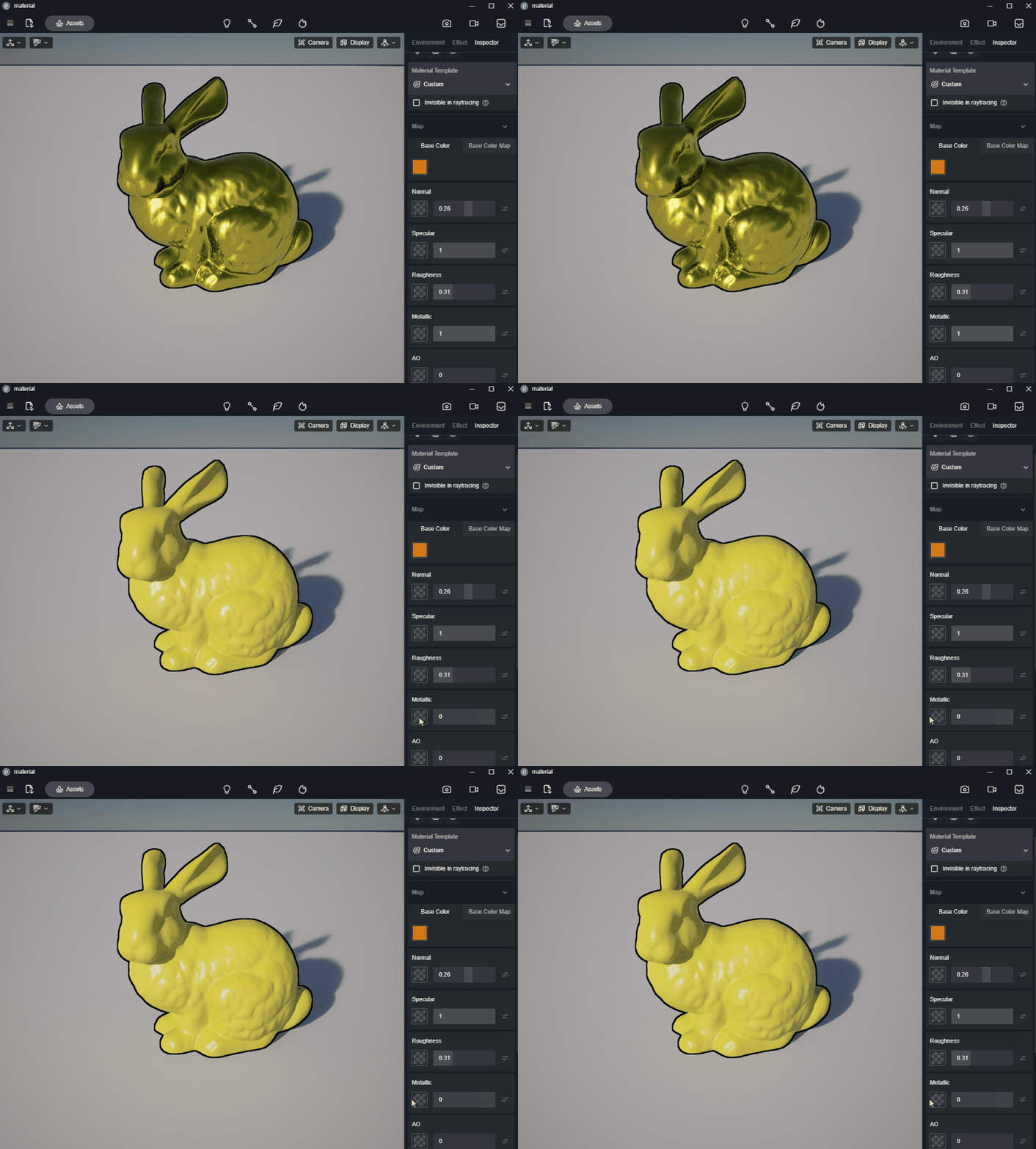
When editing the material, first determine whether the material is metal or not. If the material is metal, the metallic value is set to 1. If the material is non-metal, the metallic value is set to 0.
What is the purpose of the metallic values between 0 and 1?
Since the majority of materials are either metal or non-metal, why the metallic control is a continuous slider from 0 to 1? Why not design it as a switch? This is a question that many users will have. It is also a topic that is well worth explaining.
The metallic value of a pure metal material should indeed be 1. However, if the metal is covered by rust and dust, in this area, it is essentially a mixture of metal and non-metal, then its macro-metallic value will be less than 1, or even close to 0. Metals covered with dust or oil, or oxidized and rusted metals are generally treated as non-metal. The metallic value of the rust will be set to 0, or a value very close to 0.
Some semiconductor materials, such as silicon and germanium, also have metallic value between 0 and 1.
In addition, in our practice, we make not only pure metal materials, but also blended materials in more cases. For example, partially rusted metal. In this case, we need to use a metallic map to define which areas are metal and which areas are dust and rust, and this is where the metallic value between 0 and 1 is very useful.
AO
Ambient Occlusion channel, many pre-made PBR material package will come with AO channel map. This map will be multiplied with the base color map to enhance the shadow in the corners and seams, enhance the details of the material.

AO Multiplier: Controls how the AO map will affect the base color map. The value range is 0-1. The AO effect is strongest when the value is 1. When the number is 0, the AO map has no effect on the material.
Emissive
Turning on the Emissive switch will cause the material to glow.
Intensity: Pull the slider to control the luminous intensity. It is also possible to define the intensity using map.
Emissive color: The specific light-emitting color can be any RGB color, or a specified color temperature.
Cast Shadow: Controls whether or not the Emissive material participates in lighting (diffuse light, to be exact) calculations. When this option is checked, the material will be visible in camera and other material reflections, but will no longer cast shadows and bounce light.
Was this article helpful?
That’s Great!
Thank you for your feedback
Sorry! We couldn't be helpful
Thank you for your feedback
Feedback sent
We appreciate your effort and will try to fix the article